Sunday 12 July 2009

Skype SDK

Now that the electronic to control the motors is working, I can focus a bit more on the software.
My robot will be able to move and take decision by itself, but I still want to be able to take control via the web.
The idea is to be able to control the moves and get video feedback. I tried many example found on the web, but all not as good as I was expecting. I want something as easy as messenger or Skype.

Then I found this: https://developer.skype.com/Download It is the Ski SDK website.
You can interface Skype wit your own application using their SDK.

After creating a Skype account for my robot and one hours playing with it, I was able to check incoming message to from Skype.
If I send the message 45;400 via Skype, my application will catch it, decode it and order the electronic to turn 45 degres then travel 400cm forward. The video feedback is very simple as it use Skype.
Then it took me another 20 minutes to create a simple application that look like a remote control for my robot. This 'remote' control is to be run on the remote side of Skype that will send the motion code 45;400 in this example.

Here is how it look like:


you can see the little remote control and Skype with the motion command sent to the robot. This solution will work in any situation where Skype works. So no need to deal with sub network or port number or this like this.

Thursday 9 July 2009

At least, I solved the com between the mini PC and the PID

After many hours trying to make the serial link between the PC and the Gamoto PID board without success, I am back with the I2C protocol.

The serial link is working fine if I only talk to one board, but when I try to communicate to the second board, it just does work.

I2c is designed to talk to multiple slave, so I guess it is better. I tried to use I2C in the past without success, but this time it is working.
I can now do the following:

- Application load a rotation angle on trajectory 2 of both PID
- Application load a distance on trajectory 1 on both PID
- Application command the PIDs to execute trajectory 2
- Wait for Trajectory 2 to be done
- Application command the PIDs to execute trajectory 1
- Wait for Trajectory 2 to be done
- Send to PIDs the SetHome signal to be reading for the next move

This move allow me to select a direction and distance via the mouse to be executed by the robot.
all move are managed by the PIDs. In case the PC crash, the PIDs will finish the move and wait.

It is a good start. There still few bugs and extra code to add, but at last, I have a robot that moves.

Tuesday 26 May 2009

Installing Windows on the robot

Today, I am testing the CPU solution
I got a converter 24V to 12V from Maplin to power the CPU and other 12V devices. It is a switched converter. it is more efficient than a simple LM7812 regulator and i can get much more power out of it.
So now, I can power up the CPU, and LCD screen to install Windows. After some simple test, I can also leave the battery charger on all the time. That's good news as I can leave the CPU on while charging the battery.
The bad news it that my LCD monitor has been damaged during all these years in storage. There is a big patch of dead pixels. That will do for now, but I may have to find another one :-)

Saturday 23 May 2009

Update... It has been a long time !

It has been a long time since my last post and since I worked on my robot. Few months ago, I ran into problemwith the USB_to_I2C interface. i could not get this interface to talk to any on my I2C devices.
Few years ago, I created a parallele to I2C interface using information from the web and it was working very well. I could talk to the Gamoto PID boards and other components such as temperature sensors, I/O interface, CAN, etc.... But this time i wanted to use USB as my new PC does not have a printer port. I was able to talk to the USB interface, but any attempt to communicate to I2C devices failed. even simple devices with simple commandes.

For the last few days, I played with the COM and serial interface. I have a small board that use a MAX232 to connect the Gamoto PID to the computer in order to configure it. As this way of talking to the Gamoto is also good for controlling the motor and allow up to 7 board on the same serial signal, I decided to use it instead of the I2C.
The only limit of not using I2C is that I can only talk to the PID board, I cannot interface any other I2C devices I was planning to use.
But the PID boards provide some I/O that can be controlled via the serial port:
-2 limit switches per motor (for front left/right and rear left/right bumpers)
-4 analog input per motor (possible for temp sensor, battery monitoring, Sharp distance sensor, etc...)
So it is not so bad.
I am not working on a basic interface that will allow me to give simple direction and distance order and the robot should execute then.

Thursday 12 March 2009

Power control board

Because the chassis of the robot is based on a electric wheelchair, the motors work on 24volts, there is space for 2 batteries and space in the middle of 20cm x 24cm x 17cm. This is big enough to fit all the motor controllers, the PID and the few extra modules I need to distribute the power to the rest of the robot. Here a a draft of what the board does.


- The batteries are linked together to provide 24v. Batteries are fitted with fuses.

- The relay R1 controls the power on the motor. This relay will also be my emergency stop in case the robot goes wild. This way, I can stop the motor without stopping the rest (PC, logic, sensors, etc...)

- The relay R2 controls the power to the rest (PC, logic, sensors, etc...).
These two relays can switch up to 30 amps

- A first voltage regulator (reg1) provide 12v to the PID
I've created this module with bits I had. Took me 10 mins. This is just a 7812 voltage regulator mounted on a heat sink.


- A second voltage regulator (reg2) provide 5v to the I2C but. This module also provide 6 sockets for the I2C bus. That will allow me to plug the 2 PID, the PC and 3 other I2C devices such and temperature sensor or ultra sound ranger.
This module comes from a previous robotic project.

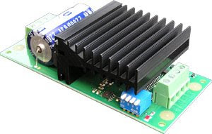
- Then the PIDs from Gamatronix and the MD03 modules from Devantech


Here is how it looks like one every thing in fitted together:

All modules are fixed on a perplex sheet. There is a second level to hold the PIDs and 5v/I2C modules.

Quadrature optical encoders for my motors

The two motors on the wheel chair are fitted with a braking system. This system lock the motors when no power is applied to them. I guess, you do not want the chair to move out of control when the battery is flat. But for me, these brakes are not required and need to be removed.
The good thing, it that I will be able to fit quadrature optical encoder where the brakes were and fit the protection back.
The encoder will provide position, and speed to the PID controller. The PID requires signals from the motors so it can control the motor in acceleration, speed and position with great accuracy. This is the idea:


Two sensors will detect the increment of the disc fitted on the motor's axis. The difference between the signal provide the sense.


A quadrature encoder provides 2 signals, frequency provide the speed. A search on google will provide much more details. I could have built them myself, but I found 3 of these encoders on eBay for a pound, so better this way. Here is one of them:
In fact, I build similar encoder a couple a year ago with infrared led and sensor. It was working, but they were big and not as good as these one.

This is how I am planning to fit them:

And this is how they fit:

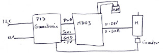
For the control, I will then use the PID controller from Gamatronix and the motor controller MD03 for more power. The PID controls the MD03 in 0-5v + sense. The encoders send back the signals to the PID. The PID are controlled via a I2C bus linked to the computer. Here is how it works:

I started to test this solution. So far, so good. I can control the wheels speed and position. I am planning to control the wheels using position mode so like this, if the PC crash, the PID will stop at some stage as no new position is received. The PID also include switch limit input that will be linked to a front and back bumper. This way, the PID will stop the motor if the robot crash into something without the need of the program on the PC to take action.

Wednesday 4 March 2009

No progress for a week

I've been busy at work since the last time I tested the motor controllers. I did not really progress much. I just had time to think a lot and make a shopping list for parts.

My first task is to build a casing for the electronic that will control the motors and provide power to the computer. I have all the modules ready, I just need to buy a switch that can cope with 30A and a relay that can also cope with 30A. The switch will be right after the batteries, the relay will control the power to the motors. Like that, I can build a kind of emergency stop without shutting down the on board PC.

Once this is done, I will fix a plywood board on the top in order to fix the PC and the webcam. Later, I am planning to add distance sensor and a bumper.
For the PC, I have a old DELL laptop with a WiFi card and a Mini ITX PC. Both of them can run using 24V dc using a simple DC-DC converter. I still don't know which one to use. Any PC would do as all the sensors and motors are controlled via USB (PC <-> USB <-> I2C <-> sensors/motors)

Anyway, I should get more things done by the end of the coming WE and will post new pics