Thursday 12 March 2009

Power control board

Because the chassis of the robot is based on a electric wheelchair, the motors work on 24volts, there is space for 2 batteries and space in the middle of 20cm x 24cm x 17cm. This is big enough to fit all the motor controllers, the PID and the few extra modules I need to distribute the power to the rest of the robot. Here a a draft of what the board does.


- The batteries are linked together to provide 24v. Batteries are fitted with fuses.

- The relay R1 controls the power on the motor. This relay will also be my emergency stop in case the robot goes wild. This way, I can stop the motor without stopping the rest (PC, logic, sensors, etc...)

- The relay R2 controls the power to the rest (PC, logic, sensors, etc...).
These two relays can switch up to 30 amps

- A first voltage regulator (reg1) provide 12v to the PID
I've created this module with bits I had. Took me 10 mins. This is just a 7812 voltage regulator mounted on a heat sink.


- A second voltage regulator (reg2) provide 5v to the I2C but. This module also provide 6 sockets for the I2C bus. That will allow me to plug the 2 PID, the PC and 3 other I2C devices such and temperature sensor or ultra sound ranger.
This module comes from a previous robotic project.

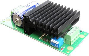
- Then the PIDs from Gamatronix and the MD03 modules from Devantech


Here is how it looks like one every thing in fitted together:

All modules are fixed on a perplex sheet. There is a second level to hold the PIDs and 5v/I2C modules.

Quadrature optical encoders for my motors

The two motors on the wheel chair are fitted with a braking system. This system lock the motors when no power is applied to them. I guess, you do not want the chair to move out of control when the battery is flat. But for me, these brakes are not required and need to be removed.
The good thing, it that I will be able to fit quadrature optical encoder where the brakes were and fit the protection back.
The encoder will provide position, and speed to the PID controller. The PID requires signals from the motors so it can control the motor in acceleration, speed and position with great accuracy. This is the idea:


Two sensors will detect the increment of the disc fitted on the motor's axis. The difference between the signal provide the sense.


A quadrature encoder provides 2 signals, frequency provide the speed. A search on google will provide much more details. I could have built them myself, but I found 3 of these encoders on eBay for a pound, so better this way. Here is one of them:
In fact, I build similar encoder a couple a year ago with infrared led and sensor. It was working, but they were big and not as good as these one.

This is how I am planning to fit them:

And this is how they fit:

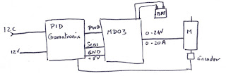
For the control, I will then use the PID controller from Gamatronix and the motor controller MD03 for more power. The PID controls the MD03 in 0-5v + sense. The encoders send back the signals to the PID. The PID are controlled via a I2C bus linked to the computer. Here is how it works:

I started to test this solution. So far, so good. I can control the wheels speed and position. I am planning to control the wheels using position mode so like this, if the PC crash, the PID will stop at some stage as no new position is received. The PID also include switch limit input that will be linked to a front and back bumper. This way, the PID will stop the motor if the robot crash into something without the need of the program on the PC to take action.

Wednesday 4 March 2009

No progress for a week

I've been busy at work since the last time I tested the motor controllers. I did not really progress much. I just had time to think a lot and make a shopping list for parts.

My first task is to build a casing for the electronic that will control the motors and provide power to the computer. I have all the modules ready, I just need to buy a switch that can cope with 30A and a relay that can also cope with 30A. The switch will be right after the batteries, the relay will control the power to the motors. Like that, I can build a kind of emergency stop without shutting down the on board PC.

Once this is done, I will fix a plywood board on the top in order to fix the PC and the webcam. Later, I am planning to add distance sensor and a bumper.
For the PC, I have a old DELL laptop with a WiFi card and a Mini ITX PC. Both of them can run using 24V dc using a simple DC-DC converter. I still don't know which one to use. Any PC would do as all the sensors and motors are controlled via USB (PC <-> USB <-> I2C <-> sensors/motors)

Anyway, I should get more things done by the end of the coming WE and will post new pics