- The batteries are linked together to provide 24v. Batteries are fitted with fuses.
- The relay R1 controls the power on the motor. This relay will also be my emergency stop in case the robot goes wild. This way, I can stop the motor without stopping the rest (PC, logic, sensors, etc...)
- The relay R2 controls the power to the rest (PC, logic, sensors, etc...).
These two relays can switch up to 30 amps
- A first voltage regulator (reg1) provide 12v to the PID

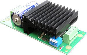
I've created this module with bits I had. Took me 10 mins. This is just a 7812 voltage regulator mounted on a heat sink.
- A second voltage regulator (reg2) provide 5v to the I2C but. This module also provide 6 sockets for the I2C bus. That will allow me to plug the 2 PID, the PC and 3 other I2C devices such and temperature sensor or ultra sound ranger.

This module comes from a previous robotic project.
- Then the PIDs from Gamatronix and the MD03 modules from Devantech


No comments:
Post a Comment